Industrial Consultancy & Sponsored Research (IC&SR) , IIT Madras

A System and Method for Measuring Cutting-edge Radius of Edged Tool

Categories for this Invention

Category: Applied Mechanics & Mechanical Engineering/Photonics/Advance Material & Manufacturing

Industry: Optics Manufacturing, Research labs, universities.

Application: Ultra-precision machining for SCD Tool in machining optical surfaces.

Market: The global market size is valued at 24.30 billion in 2022 and is predicted to reach 59.74 billion by the year 2031 at a 10.73% CAGR during the forecast period for 2023-2031.

Image Gallery

Problem Statement

  • Single crystal diamond (SCD) tools are used in ultra-precision machining for machining optical surfaces with nanometric surface finish.
  • The machined surface finish quality depends on the tool’s cutting-edge radius.
  • Optical 3D sensors are used for measurement but due to light diffraction phenomenon, nanometric resolutions cannot be measured.
  • Some systems used a scanning electron microscope chamber, due to SCD tool being a non-conductive material, thereby resulting in charging effect and to overcome this effect, the cutting edge of the SCD tool was coated in gold to measure edge radius.
  • However, this resulted in non-uniform thickness, thereby resulting in limiting the accuracy of the tool.
  • Further, in AFM technique the alignment of SCD tool tip with the AFM scanner and it is time consuming , expensive, and also holds a high risk of AFM tip breakage.
  • There is need for a system and method for measuring cutting-edge radius on single-crystal diamond tool for precise quantitative measurement.

Technology

  • A system for measuring cutting-edge radius on an edged tool comprising:
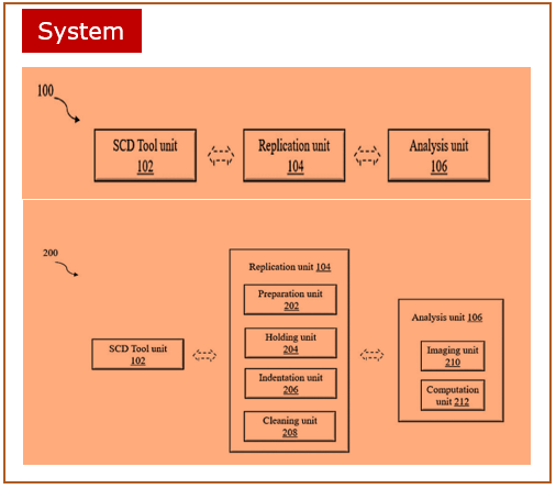
  • Edged tool positioned in a tool holder.
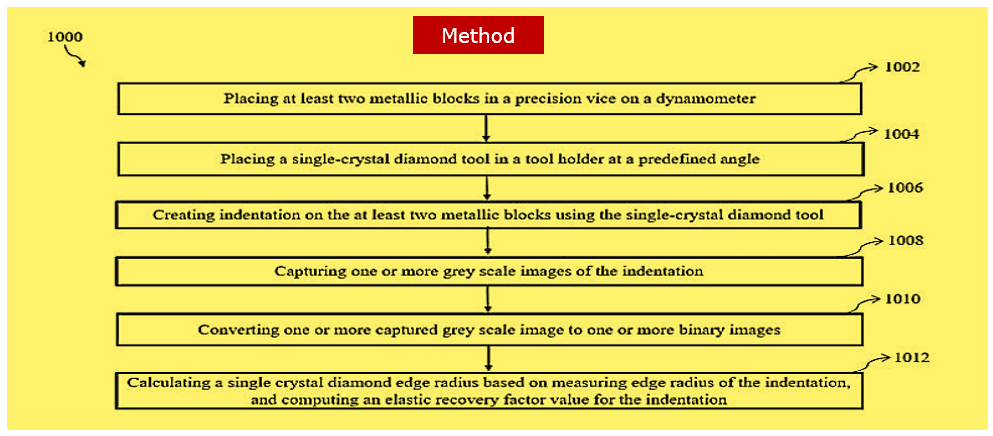
  • A replication unit  has a holding unit  configured to receive at least two metallic blocks.
  • An indentation unit  configured to forge an indentation of predefined depth by thrusting and retracting the edged tool onto the at least two metallic blocks forming the indentation
  • An imaging unit  configured to capture one or more images of the indentation and convert the one or more captured indentation images to one or more binary images.
  • A computation unit  configured to calculate an edge radius for the edged tool based on a calculated elastic recovery factor value and an intended radius experimental value.

Key Features / Value Proposition

  • An accurate edge reversal method for edged tool edge radius characterization.
  • Provide an indentation of sharp cutting edge of the edged tool at a predefined angle on at least two metallic blocks.
  • Provide a cross-section of the indentation on the at least two metallic blocks by replicating and analyzing a cutting edge profile of the edged tool.
  • Creating a replica of the cutting-edge profile by indenting the smooth surface of the substrate, without damaging the cutting-edge.
  • Cutting-edge radius of the SCD tool typically from 10 nanometers.
  • Cost efficiency in optics surface finish manufacturing.

Questions about this Technology?

Contact For Licensing

sm-marketing@imail.iitm.ac.in
ipoffice2@iitm.ac.in

Research Lab

Prof. Sathyan Subbiah

Department of Mechanical Engineering

Intellectual Property

  • IITM IDF Ref. 2299

  • Patent No: IN 533356

Technology Readiness Level

TRL – 4

Technology validated in lab scale.

error: Content is protected !!